Navigation via space junk, magnetic fields, and gravity

As the demand for reliable navigation in GNSS-denied environments increases, industry is developing a range of navigation technologies designed to work with and greatly improve the accuracy of conventional inertial navigation systems. Honeywell Aerospace revealed some of their forthcoming technologies.

Artificial space objects have become so common above the Earth, navigation using these as reference points is now possible.
Artificial space objects have become so common above the Earth, it is now possible to navigate using them. This includes both active and dead satellites, and large pieces of space junk such as jettisoned rocket stages. (Spacejunkview.com)
Mark Cazalet

At the AUSA 2026 exhibition, Warsight got the chance to sit down with Honeywell Aerospace to discuss some of the company’s new and in development technologies intended to allow positioning, navigation, and timing (PNT) in the absence of a global navigation satellite system (GNSS).

The need for reliable PNT in GNSS-denied environments has grown more acute, and has been particularly highlighted in Ukraine, where both sides have employed sophisticated electronic warfare (EW) capabilities. Notably, Russia’s jamming capabilities have proven capable of successfully disrupting the navigation capabilities of various GNSS-guided munitions, such as M982 Excalibur guided 155 mm rounds, M30 GMLRS guided rockets, GLSDB glide munitions, bombs fitted with JDAM guidance kits, and even platforms using the Starlink network.

Finding ways to maintain PNT in the absence of GNSS is therefore something of a priority for keeping forces combat effective on current and future battlefields. This is especially the case as greater investment in signals intelligence (SIGINT) capabilities is making signal emission an increasingly risky act.

Inertial navigation systems (INSs) have long provided a self-contained means of navigation and cannot be jammed. However there are limits to their accuracy without correction, even among high-end modern examples, such as those based on ring laser gyroscopes (RLGs), fibre optic gyroscopes (FOGs), or Micro-Electro-Mechanical Systems (MEMS) gyroscopes.

All INSs eventually ‘drift’ in accuracy – accumulating small measurement errors over time and distance. Correcting these errors to bring INSs back into line requires a secondary positional reading, and often GNSS has been the default.

Ann Witt, Senior Director for Business Development – Advanced Programs at Honeywell Aerospace summarised the core problem:

“So inertials will generally drift at some rate, and GPS is used to bring it back to that more accurate position. It allows it to do longer missions,” she explained, “from both from an accidental perspective and from an adversary perspective, we are seeing interferences in the frequency spectrum of GPS [Global Positioning System]. And what that does, from an inertial systems perspective, is it takes away its ability to update itself and to get fixes.”

As such, the company looked for alternate means to correct for INS drift. “So in understanding the amount of time that it’s not going to have GPS and not get those updates, we started looking into what technologies we could use,” Witt said. She added, “currently we have we have taken a few technologies to a higher TRL [Technology Readiness Level] of 5+, some of them 6.”

These ‘alternative’ navigation systems are all intended to improve INS accuracy, either by correcting for drift, or as Witt explained, “to provide [the INS] an initial seed position because it allows it to align. So, a gyrocompassing system will align at a spot. Basically, the sensors feeling the spin of the Earth, and how things are going will determine ‘this is how the gyro should be looking right now’, based on the position that you give it.”

Among the many technologies discussed, three in particular stood out: celestial aided navigation, magnetic anomaly aided navigation, and gravimetric navigation.

Celestial aided navigation: “It’s not your father’s star tracker”

One of the more intriguing of the systems described was the new Celestial Aided Navigation system – referred to as CNAV. While celestial navigation as a principle has existed since at least 2000 BC, and undergone much improvement over the millennia since, with innovations such as the sextant still taught to navigators today, Honeywell Aerospace’s CNAV approach takes advantage of a relatively recent development – satellites and space junk.

“So instead of just looking at the stars, which can get you 100, 200 metres [accuracy], we actually look at the star and then watch a space object go past it, and then we remap it that way so we can get the accuracy down to sub-100 metres” Witt explained.

She added that these space objects would include “satellites, a large discarded body. It’s not like something teeny, not all the space debris, but larger space debris. So, things that are mapped, because we have to have to have the mapping of that thing.”

Space objects (also referred to as ‘resident space objects’ – RSOs) are continuously monitored, with various entities including the US Strategic Command (USSTRATCOM) Space Surveillance Network (SSN), NASA, the ESA, and orbital intelligence companies such as LeoLabs gathering the primary tracking data. The data is publicly available through databases such as The United Nations Office for Outer Space Affairs (UNOOSA) or Privateer, and various others.

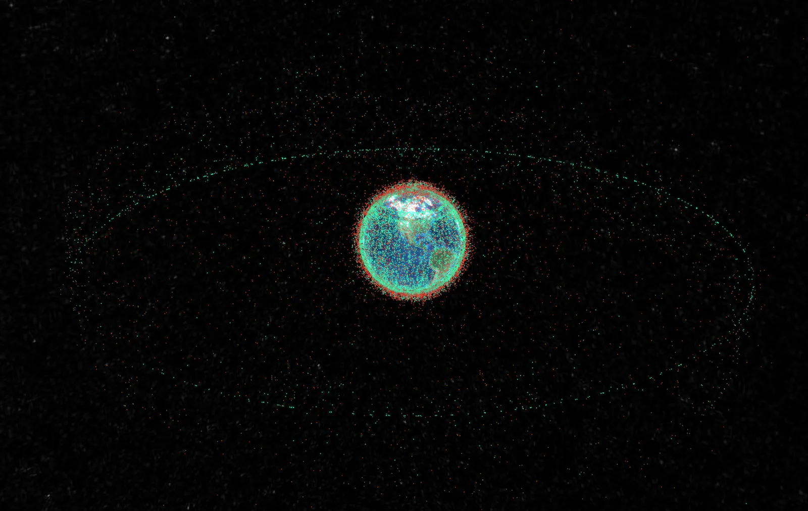
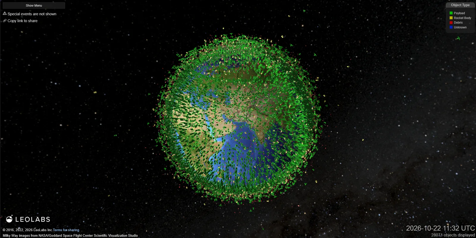
As this image from LeoLabs shows, there are many tens of thousands of viable space objects in the sky above Earth, many of which have fairly stable orbits. This provides a large pool of resources to draw upon for use as reference points in celestial navigation.
As this image from LeoLabs shows, there are many tens of thousands of viable space objects in the sky above Earth, many of which have fairly stable orbits. This provides a large pool of resources to draw upon for use as reference points in celestial navigation. (LeoLabs)

Databases such as these can provide the real-time positions orbital data, and type classifications for various space objects, including active satellites, satellites in graveyard orbits, spent rocket stages, or pieces of either. Objects such as these are often in stable orbits, and so can therefore effectively serve as predictable landmarks for navigation purposes.

According to the ESA, there are around 68,450 space objects measuring ≥10 cm in size, of which many are significantly larger and visible at greater distances. These larger objects provide a sizeable pool of potential objects to use as landmarks, which is what Honeywell Aerospace’s celestial navigation system takes advantage of. As to the sensor used, Witt confirmed, “it’s a camera.”

Witt expounded the key principles along which the navigation system worked: “So you’re looking up at a fixed star, and then you basically you have the ephemeris type data of the object, the sunlight or whatever, because you know what part of the sky you’re looking at it, and then as [the space object] goes by, you’re able to say, ‘okay, we went by the star like this’, and with those distances, you know where the star is, you know where the space object is. That’s how you’re able to know the position.”

So how would this kind of navigation system work in practice for something like a missile or aircraft? First, it would require uploading data of reference star positions to confirm which part of the sky it is seeing (plate solving), along with the ephemeris data of reference satellites/space junk relevant to when and where it will be operating. Through this, the camera will know which part of the sky it is looking at, and will be able to identify satellites or space junk based on their observed positions corresponding to their orbital data.

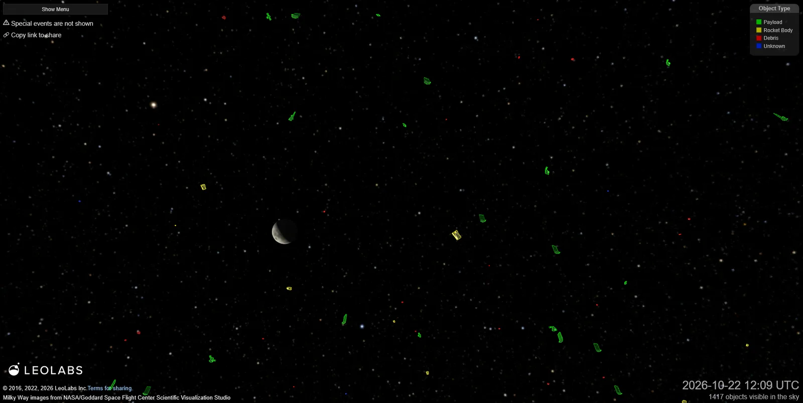
This ground view of space objects from LeoLabs serves to illustrate how Honeywell Aerospace’s celestial navigation works in principle, by showing you roughly what the camera would be looking for – capturing space objects crossing in front of the field of stars used as a fixed reference point, and comparing their observed positions with those it would have expected to see based on the INS estimate.
This ground view of space objects from LeoLabs serves to illustrate how Honeywell Aerospace’s celestial navigation works in principle, by showing you roughly what the camera would be looking for – capturing space objects crossing in front of the field of stars used as a fixed reference point, and comparing their observed positions with those it would have expected to see based on the INS estimate. (LeoLabs)

Once the aircraft or missile is in motion, the camera stares at a given patch of space, and because it knows which part of the sky it is seeing, the stars effectively serve as a coordinate grid. The camera then takes repeated snapshots of the positions of known satellites and/or space junk as these objects move against the background patch of stars.

The system can then measure the angular separation between multiple space objects and the background stars at various time intervals. These are then compared to the angular measurements the camera would have ‘expected’ to see based on the INS position estimate. The difference between the two is then fed into a filter running on an onboard computer, which converts the difference into a correction to the INS positional estimate. Because the INS will continue to drift over time, it will require continued positional updates to retain accuracy.

According to a Honeywell Aerospace brochure, the CNAV system also has a reversionary ‘stars only’ navigation mode when space objects are unavailable. However, with a stated circular error probable (CEP) of <1 nautical mile per hour (<1,852 m/hr), this mode provides significantly less positional accuracy compared to when space objects are added into the mix, where a circular error probable (CEP) of <25 m becomes possible.

The new CNAV is certainly an interesting piece of technology. However, taking a step back, the fact that there are now so many satellites and pieces of space junk orbiting Earth that humanity can now use them to reliably navigate, should probably serve as a warning of just how crowded and messy the sky above our planet has become. Though while they continue to exist, they may as well be put toward some kind of useful purpose, and GNSS-free navigation would certainly count.

Magnetic anomaly aided navigation: Sensing the field lines

Another interesting technology discussed by Honeywell Aerospace involved the use of using the Earth’s magnetic field to improve the accuracy of INSs. This is the basis of the company’s Magnetic Anomaly Aided Navigation (MAAN), also referred to as ‘MagNav’.

Witt explained that MAAN worked by “map matching to a magnetic mapping, so it would be feeling that magnetic field.” Warsight asked if this would be problematic because magnetic fields change over time, to which Witt responded “they’re not so volatile, because we’re looking at the local field map as opposed to the Polar magnetic maps.”

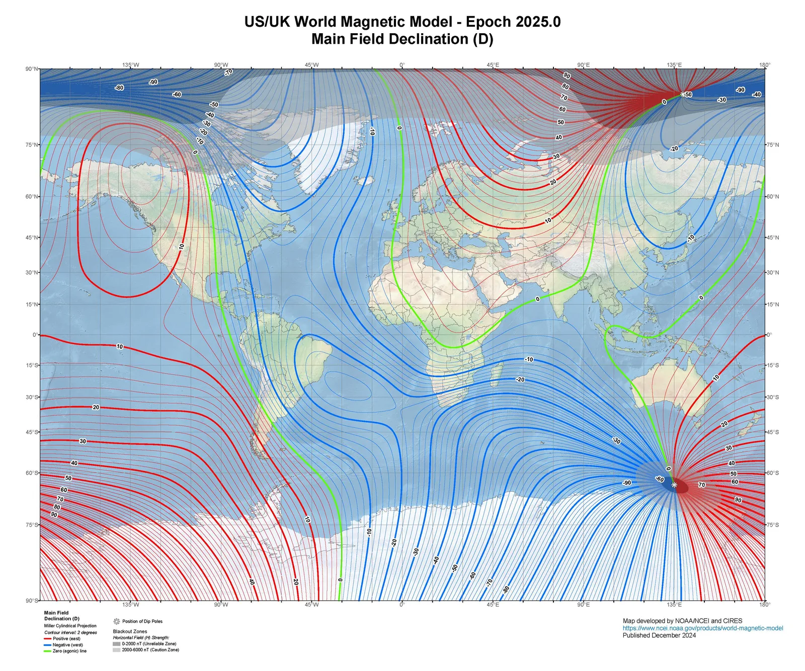
An example magnetic field map published in December 2024, generated by NOAA/NCEI and CIRES. Maps such as these show the sum of all magnetic fields, which include the main magnetic field generated by the core, the crustal field generated in the crust and mantle, and the disturbance field from electrical currents flowing in the upper atmosphere and magnetosphere.
An example magnetic field map published in December 2024, generated by NOAA/NCEI and CIRES. Maps such as these show the sum of all magnetic fields, which include the main magnetic field generated by the core, the crustal field generated in the crust and mantle, and the disturbance field from electrical currents flowing in the upper atmosphere and magnetosphere. (NOAA, NCEI and CIRES)

Magnetic field maps of the earth have been developed by various entities including the US National Geospatial-Intelligence Agency (NGA), the UK Defence Geographic Centre (DGC), the British Geological Survey (BGS), the International Association of Geomagnetism and Aeronomy (IAGA), the United States Geological Survey (USGS), and the National Oceanographic and Atmospheric Administration (NOAA).

Such magnetic field maps are generated using data gathered from magnetic observing systems, which can be ground-based observatories, or space-based, such as the ESA’s SWARM satellite mission.

Such maps can then be uploaded onto a navigation system equipped with a highly sensitive magnetometer, and on that count, a Honeywell Aerospace representative confirmed that the company was developing a quantum magnetometer. These sensors can then derive positional information from sensing the magnetic field lines and comparing them to the magnetic map stored on-board.

In response to a Warsight question about magnetic map accuracy, Witt replied, “Not all of them are high-accuracy maps, so that’s actually one of the complications in the magnetic environment. So that’s something actually that we are also working on.”

With regards to the accuracy of the MAAN system as a whole, Witt said, “it will match a region, but it will have an error, and it’s not a small error. We’re not talking about GPS, you know, five metres or less type of error. We’re talking about actually a pretty large error. So, it will get you in an envelope.”

So how big is this envelope? According to a Honeywell Aerospace brochure, the MAAN system is accurate to a CEP of under 200 m. Putting this figure into context, a June 2025 paper from the Lawrence Livermore National Laboratory (LLNL), How Quantum Sensing Will Help Solve GPS Denial in Warfare classified Magnetic Navigation (MagNav) within an accuracy band of 100 m to 1,000 m, noting, “accuracy is dependent on velocity, altitude, correcting for the vehicle’s magnetic field, and the map’s quality/resolution. Navigation will deteriorate in a space with minimal anomaly features.”

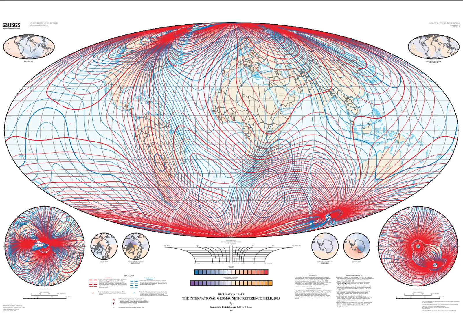
A USGS magnetic field map of the Earth in 2005.
A USGS magnetic field map of the Earth in 2005. (USGS)

The LLNL report also provided relevant context on MagNav practicalities, noting, “there are other, natural, time-varying sources of magnetic fields (such as space weather and currents in the Earth’s mantle) that would need to be accounted for when utilizing magnetic maps. Fortunately, there is a sweet spot between a couple hundred meters and a few kilometers above Earth’s surface where contributions from time-dependent magnetic fields and man-made structures are minimized and the crustal anomaly field shines through. This makes MagNav particularly attractive for arial vehicles and guided munitions, provided the quantum sensors can meet the stringent SWaP [size, weight, and power] requirements they require. MagNav is still possible close to Earth’s surface, though accuracy may be more limited.”

Gravimetric navigation: Feeling the hidden topography of gravity

The last navigation technology discussed with Honeywell Aerospace was Gravimetric navigation, often abbreviated to GravNav.

In terms of the applications of the technology envisioned by Honeywell Aerospace, Witt said the main use case of the technology would be for underwater navigation. The company further added that “this approach is particularly relevant to long-endurance underwater missions where traditional GNSS-based navigation is unavailable.”

So how does it work? Well, like MagNav, it relies upon pre-loaded maps, only in this case measuring localised changes in the strength of the Earth’s gravitational field.

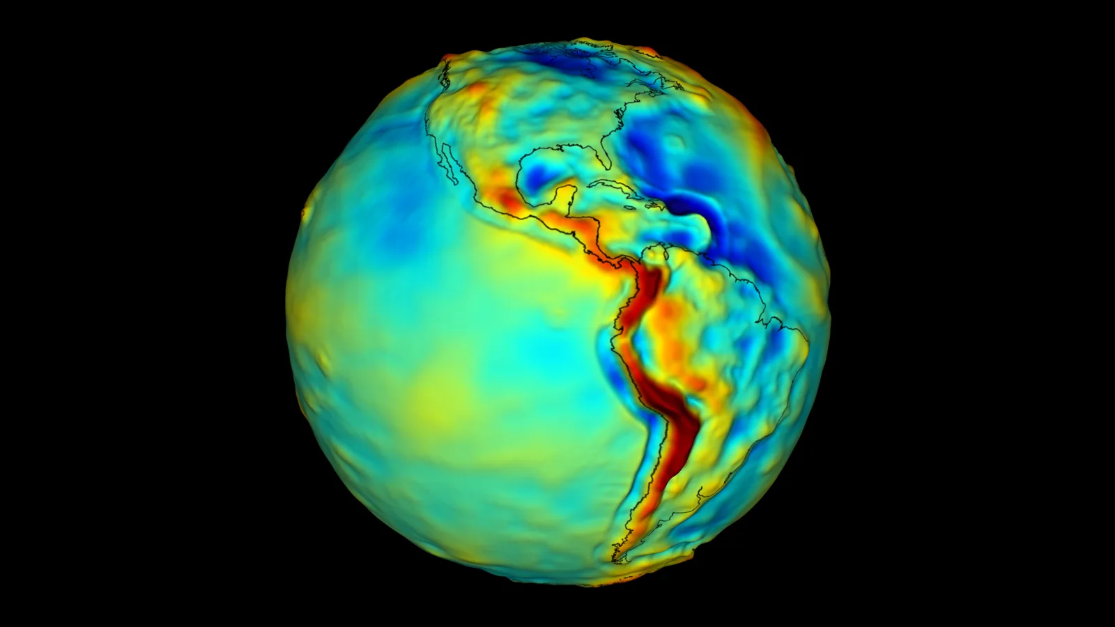
According to NASA, “varying surface topography and the continuous movement of water cause different parts of the globe to have more or less mass than other regions.” These differences can be recorded and mapped. Satellites such as NASA’s twin GRACE satellites and the ESA’s GOCE satellite have mapped Earth’s gravity field (from 2002-2017, and 2009-2013 respectively), discovering localised variations and monitoring how it changes over time.

A false-colour gravimetric map of Earth, showing localised changes in the force of gravity. Warm colours (red, orange, yellow) represent areas with strong gravity. Cool colours (green, blue) represent areas with weak gravity. As the map shows, Mountain ranges have a high concentration of mass, and therefore have a stronger gravity field, while ocean trenches, have a low concentration of mass, and therefore have a weaker gravity field.
A false-colour gravimetric map of Earth, showing localised changes in the force of gravity. Warm colours (red, orange, yellow) represent areas with strong gravity. Cool colours (green, blue) represent areas with weak gravity. As the map shows, Mountain ranges have a high concentration of mass, and therefore have a stronger gravity field, while ocean trenches, have a low concentration of mass, and therefore have a weaker gravity field. (NASA)

So how accurate is it? While Honeywell Aerospace did not state a figure during the conversation, an estimate is available from the LLNL report, which classified GravNav within an accuracy band of 2,000 m to 10,000 m, adding that accuracy is “limited by the resolution and quality of available gravitational anomaly maps. Performance will also deteriorate in places with minimal gravitational anomaly features.”

The LLNL report also explained some of the current limitations of the technology, noting: “GravNav shares many characteristics with MagNav. Like Earth’s magnetic field, the strength of Earth’s gravity varies slightly by location due to terrestrial features like mountains, valleys, and heavy-metal deposits. However, gravitational changes are weaker and occur over longer distances than magnetic anomalies. The sparse signals limit GravNav’s precision and require more measurement time and distance to be covered (tens of miles, or hours to days) for gathering sufficient data to deliver a location reading.”

However, the report also noted that the new generation “quantum gravimeters and gradiometers have already surpassed their classical counterparts in sensitivity, fieldability, and accuracy, promising a substantial upgrade to the utility of GravNav.”

The report further added, “atomic gravimeters are becoming increasingly compact and ruggedized, require no recalibration, and already offer better long-term stability and higher precision than their classical counterparts despite being a relatively immature technology.”

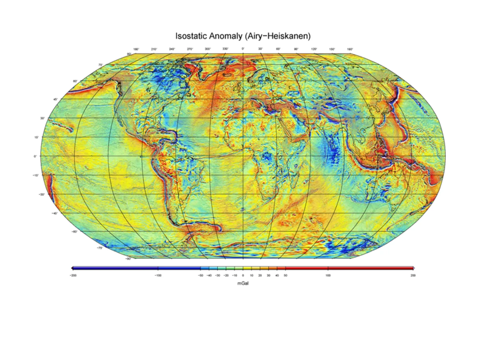
The Bureau Gravimétrique International (BGI) offers several different gravimetric map models, with up to 1 nautical mile (1,852 m) resolution.
The Bureau Gravimétrique International (BGI) offers several different gravimetric map models, with up to 1 nautical mile (1,852 m) resolution. (BGI)

It is quite plausible that Honeywell Aerospace’s envisioned gravimetric sensor is intended to be a quantum gravimeter. Prior to Honeywell’s 2025 split into three companies – Honeywell Technologies, Honeywell Aerospace, and Solstice Advanced Materials – the company operated Sandia National Laboratories. Sandia has been known to have worked on numerous gravimetry technologies, including quantum gravimetry, since at least the mid-2010s. After Honeywell’s split, Sandia came under the auspices of Honeywell Aerospace.

Honeywell Aerospace are not the only ones looking to quantum gravimetry. On 27 August 2026, Australian quantum technology company Q-CTRL claimed to have conducted a world first field demonstration, in which a maritime vessel  achieved positioning accuracy of 1 nautical mile (1,852 m) during a series of fully GNSS-independent gravity map matching navigation trials in the Coral Sea, off the East coast of Australia. For the tests, the vessel’s gravimeter accuracy was enhanced through the use of Q-CTRL’s Ironstone Opal, which worked to counteract the effect of environmental noise on the system.

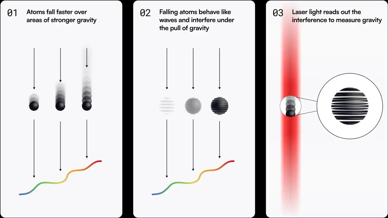
This Q-CTRL graphic demonstrates how gravity at a given location is measured.
This Q-CTRL graphic demonstrates how gravity at a given location is measured. (Q-CTRL)
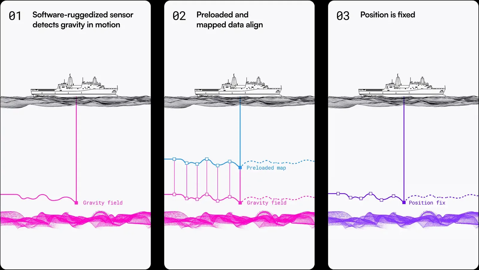
This Q-CTRL graphic demonstrates the basic principles behind gravity map matching techniques.
This Q-CTRL graphic demonstrates the basic principles behind gravity map matching techniques. (Q-CTRL)

Building a GNSS-denied navigation architecture

Alongside CNAV, MAAN, and GravNav, Witt explained that the company is working on multiple other sensors working toward the same goal of navigation in GNSS-denied environments.

These included a doppler Honeywell Radar Velocity System (HRVS), a doppler radar-based velocity update system small enough to be mounted on a small-medium sized drone; a “coin-sized” atomic clock; vision aided navigation; terrain matching; navigation via low-Earth Orbit (LEO) satellite constellation (similar in principle to normal GNSS, but with stronger signals transmitted over shorter distances), and various others.

As with the systems described previously, these other navigation systems are fundamentally intended to improve INS accuracy in various ways.

Tying all these disparate systems together is the Honeywell Alternative Navigation Algorithms (HANA) software, which Witt explained “is a sensor fuser that basically takes these different inputs and it understands their error rate, so it aligns those to the inertial and determines which it’s going to use at which time, and then it also would alert the user to how far off they might be from position.”

This is not to be confused with the company’s other HANA (Honeywell Alternative Navigation Architecture), which is essentially the term used to refer to the company’s entire GNSS-denied navigation product portfolio.

As EW jamming and spoofing continue to increase in sophistication, the ability to reliably navigate in GNSS-denied environments will become increasingly necessary. Most of the technologies discussed here are not quite ready for fielding yet, but they’re not far from completing development. As such, they represent some of the cutting-edge possibilities for designers coming down the pipeline, providing a glimpse of what we can begin to expect to see equipping munitions and platforms of the not-too-distant future.

Share post

You may be interested in

Categories

All NewsEM/CyberSpace

Used tags

CNAVElectronic WarfareEWGNSSGravNavMagNavNavigationPNTSatellitesSIGINT

Similar posts